


 English
 русский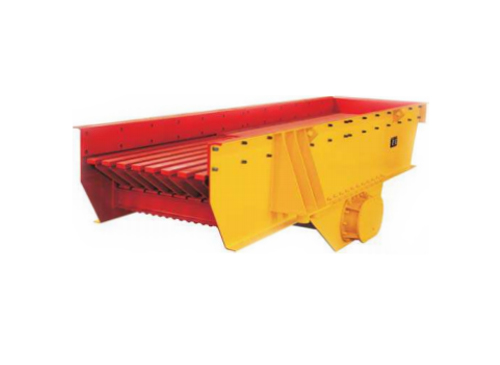
Put a jaw crusher and a cone crusher on the same granite deposit and both will break rock. Put them in the same slot of a flowsheet and one of them will fail the job. That is the practical answer behind the question "which is better, a cone crusher or a jaw crusher" — the comparison only becomes meaningful once you kn...
Mining Feeding Equipment Manufacturers
About Us
Shanghai Sanming Mining Equipment Manufacturing CO., LTD.
Sanming is an international Mining Machinery Equipment Supplier that integrates R&D, Manufacturing, and Sales of Rock Crushing&Screening equipment, as well as Sand Making, Sand Washing, and Grinding equipment. Sanming has passed ISO9001 quality system certification.
As China Mining Feeding Equipment Manufacturers and OEM Rock Stone Feeding Equipment Suppliers, our equipments are widely used in the fields of Sand and Gravel Aggregate processing, Mining, and Construction Waste Resource utilization.
"Sanming" brand equipments are not only distributed in nearly 30 provinces in China, but also exported in large quantities to multiple countries in Central Asia, the Middle East, South America and Africa, and has received unanimous praise from users. Our main production base is located in Qidong (Shanghai Pudong New Area Industrial Park). We warmly welcome your visit to our factory.
News & Blogs
-
-
When a crushing plant is being planned or upgraded, the cone crusher usually appears near the top of the equipment list. It works in the secondary, tertiary and sometimes quaternary stage, turning coarse rock into the consistent fractions that the rest of the plant depends on. But a "cone crusher" is not a single mach...
-
Shanghai Sanming Mining Equipment Manufacturing Co., Ltd. has confirmed its participation in bauma CHINA 2026 — the International Trade Fair for Construction Machinery, Building Material Machines, Mining Machines and Construction Vehicles. As one of the most influential trade fairs in the engineering machinery industry...
Feeding Equipment Industry knowledge
Fundamentals of Mining Feeding Equipment in Material Handling
In industrial bulk material processing, Mining Feeding Equipment serves as the foundational interface between raw material extraction and downstream processing circuits. Whether handling run-of-mine (ROM) ore directly from haul trucks or reclaiming processed aggregates from surge tunnels, the primary function of a feeder is to regulate the volumetric flow of materials into crushers, screens, and conveyor belts. Without controlled feeding, downstream equipment faces chronic operational inefficiency characterized by either devastating surge loads that choke crushers or starvation periods that underutilize plant capacity.
The strategic placement of high-quality Mining Feeding Equipment directly dictates the mechanical availability and longevity of the entire processing plant. When massive, high-impact rock blocks are discharged from dump trucks, they possess immense kinetic energy. Advanced equipment absorbs these severe impact loads, dampens structural shock, and transitions the chaotic, intermittent dumping action into a continuous, uniform material stream. This steady state is crucial for maintaining the optimal choking level inside jaw and cone crushers, which maximizes inter-particle crushing efficiency while reducing specific power consumption.
Furthermore, raw mineral deposits rarely present a uniform composition. Material streams typically consist of high-abrasion ores mixed with high-moisture fines and sticky clays. This material variation introduces severe processing risks, such as material bridging across hopper throats or stickiness that halts production. As a certified manufacturer compliant with ISO9001 quality system standards, Shanghai Sanming Mining Equipment Manufacturing CO., LTD. engineers its heavy-duty Mining Feeding Equipment to operate continuously under these harsh mechanical stresses. By utilizing heavy-duty structural designs and optimized vibration profiles, modern feeding systems ensure consistent material progression regardless of variations in moisture content or particle size distribution, stabilizing the production line's overall throughput.
On a systemic level, the reliability of the feeder directly influences the wear patterns of downstream conveyor belts. A fluctuating feed rate causes material to pile up unevenly, leading to belt mistracking, edge damage, and premature belt degradation. Conversely, a smoothly regulated bed depth supplied by precise Mining Feeding Equipment minimizes the relative velocity differential between the material and the belt at the loading point. This alignment drastically reduces the scouring action of sharp rocks against the rubber top cover, extending the operational life of the entire conveyor network and lowering the total cost per ton of material handled.
Classification and Technical Selection of Mining Feeding Equipment
Selecting the appropriate class of Mining Feeding Equipment requires a thorough analysis of material characteristics, plant layout, and volumetric requirements. Industrial feeders are broadly categorized into four primary types, each tailored to distinct operational phases from primary scalping to precise fine blending.
Heavy-Duty Linear Vibrating Feeders
Linear vibrating feeders rely on the principle of directed linear acceleration. Driven by twin-shaft mechanical exciters or synchronized motors, the feeder trough moves at a specific angle relative to the horizontal plane. This movement causes the material bed to micro-hop forward in a uniform, fluid state. This continuous progression minimizes friction between the material and the trough liner, drastically reducing abrasive wear while delivering a highly predictable volumetric feed rate to subsequent processing stages.
Grizzly Feeders for Primary Scalping
Positioned directly ahead of primary jaw or gyratory crushers, Vibrating Grizzly Feeders are dual-function machines. They combine controlled material transport with pre-screening via a series of heavy, tapered grizzly bars at the discharge end. As the material moves across these bars, under-sized fines drop through the gaps before entering the crusher. This process bypasses materials that are already smaller than the crusher's closed-side setting, which prevents over-crushing, minimizes the creation of unmarketable ultrafines, and expands the net processing capacity of the primary station.
Apron Feeders for Extreme Impact
For the most punishing applications involving high-drop, high-tonnage dumps of large, unscalped rock blocks, apron feeders represent the industry standard. Constructed with heavy-duty tractor-type chains, rugged support rollers, and overlapping manganese or steel flight pans, these machines operate via high-torque hydraulic or electromechanical drives. Unlike vibrating units, apron feeders do not rely on acceleration to move material; instead, they function as heavy-duty, slow-speed slot conveyors that mechanically pull sticky, wet, or extremely heavy material out from under high-pressure hopper configurations.
Electromagnetic and Belt Feeders
When processing moves downstream into secondary crushing, sand-making, or fine-grinding circuits, precision replaces raw impact absorption as the primary operational requirement. Electromagnetic vibratory feeders operate at low amplitudes and high frequencies, allowing for near-instantaneous adjustment of material flow for automated batching systems. Similarly, heavy-duty belt feeders utilize variable speed belt drives under surge bins to extract fine aggregates or minerals smoothly, providing an ideal, non-pulsing feed to downstream sand washing plants or milling circuits.
Engineering Selection and Application Scope
To match these distinct mechanical behaviors with specific geological and structural demands, Shanghai Sanming Mining Equipment Manufacturing CO., LTD. supplies customized solutions across all four major equipment categories. By integrating specialized R&D with field data collected from aggregate and mining projects, the company ensures that the selected Mining Feeding Equipment seamlessly aligns with the physical traits of the ore, whether handling massive granite boulders or highly cohesive construction waste.
Comparative Technical Parameters: Feeder Classification
The table below outlines the core operational envelopes for these four primary classes of Mining Feeding Equipment, aiding engineering teams during early-stage plant layout selection:
| Parameter / Feature | Heavy-Duty Linear Vibrating Feeder | Vibrating Grizzly Feeder | Apron Feeder | Electromagnetic / Belt Feeder |
| Primary Function | Bulk transport & surge control | Simultaneous feeding & pre-screening | Heavy extraction under high hopper pressure | Precision downstream flow regulation |
| Max Material Size | Up to 800 mm | Up to 1,200 mm | Up to 1,500+ mm | Fine to medium (<150 mm) |
| Moisture / Clay Tolerance | Moderate | Moderate (risk of blinding bars) | Very High (handles sticky clay) | Low to Moderate |
| Typical Capacity Range | 100 - 600 t/h | 200 - 1,000+ t/h | 150 - 3,000+ t/h | 10 - 400 t/h |
| Dominant Wear Mechanism | Sliding abrasion | Sliding abrasion & heavy impact | Extreme impact & compression | Light sliding abrasion |
High-Performance Design Attributes and Key Technical Specifications
To withstand the violent forces inherent in mining and quarrying environments, high-performance Mining Feeding Equipment incorporates specialized mechanical engineering disciplines. Three critical attributes define a structurally reliable feeder: its vibration dynamics, its wear-resistant liner integration, and its structural layout.
Excitation Sources and Vibration Dynamics
The movement of material within a vibratory feeder is governed by its acceleration profile, measured in G-forces (where 1G equals the acceleration due to gravity). For effective material progression, industrial feeders are engineered to operate within a 2.5G to 4.5G range. Generating this force requires precise balancing of the eccentric masses within the exciters.
If the excitation frequency aligns with the natural frequency of the supporting structure, destructive resonance occurs, leading to structural cracking. To prevent this, Shanghai Sanming Mining Equipment Manufacturing CO., LTD. designs its vibratory systems with high structural rigidity, ensuring operational frequencies remain far outside the resonant zone. By anchoring their R&D in strict mechanical standards, the company incorporates Variable Frequency Drives (VFD) into their engineering packages, allowing plant operators to fine-tune these frequencies in real-time to match changing material densities and optimize throughput.
Wear-Resistant Liner Technology
Because the feeding trough is subject to continuous sliding abrasion and high-velocity impacts, the base steel framework must be fully isolated from direct material contact. This is achieved using replaceable wear-resistant liners. The selection of liner material corresponds directly to the specific wear mechanism encountered in the field:
High-Manganese Steel (Mn13): Excellent for high-impact zones; this material work-hardens under impact, increasing its surface hardness while retaining its core toughness.
Hardox / Premium Quenched & Tempered Steels: Provides an ideal balance of sliding abrasion resistance and structural integrity for general-purpose applications.
Chromium Carbide Overlays (CCO): Selected for extreme sliding abrasion environments involving fine, hard mineral grains, offering a long operating life despite low impact tolerance.
Heavy-Duty Rubber or Polyurethane Liners: Used in wet sand processing or non-cohesive material handling to dampen acoustic noise and absorb structural vibration energy.
Structural Heavy-Duty Framework
Modern industrial feeders must be engineered using Finite Element Analysis (FEA) to map stress distribution during both empty and maximum-load states. The feeder pan sides are typically constructed from thick, single-plate structural steel to eliminate the stress concentrations associated with multi-piece welded joints. Following fabrication, critical weldments undergo thermal stress-relief processing to eliminate residual welding stresses. The entire assembly is then supported by a heavy-duty spring isolation system—using heavy coil springs or molded rubber blocks—designed to absorb up to 95% of the dynamic forces, preventing these high-frequency vibrations from damaging the plant's larger steel structural framework.
Technical Performance Parameters of Core Components
The choice of liner materials and mechanical structural ratings changes significantly depending on the operational tier of the machine. The following parameters demonstrate how technical specifications scale across light, medium, and heavy-duty configurations:
| Technical Specification | Light-Duty Configuration | Medium-Duty Configuration | Heavy-Duty Configuration |
| Target Material Density | Less than 1.4 t/m3 (e.g., Coal, Slag) | 1.4 - 2.0 t/m3 (e.g., Limestone) | Greater than 2.0 t/m3 (e.g., Iron Ore, Granite) |
| Operational G-Force Range | 2.2G - 3.0G | 3.0G - 3.8G | 3.8G - 4.5G |
| Default Liner Material | Polyurethane / Mild Steel | Hardox 400 / Mn13 | Hardox 500 / Chromium Carbide Overlay |
| Liner Thickness | 8 mm - 12 mm | 12 mm - 20 mm | 20 mm - 40+ mm |
| Isolation Spring Type | Standard Steel Coil Springs | Heavy Steel Springs w/ Rubber Cores | High-Dampening Solid Rubber Blocks |
| Structural Stress Relief | Optional | Recommended for Weldments | Mandatory Thermal Stress Relief |
Sub-Types and Specialized Mechanics of Industrial Feeders
Within the broader category of vibratory material handling, several distinct sub-types of Mining Feeding Equipment exist, differentiated by their drive mechanisms and structural configurations.
Vibrating Feeders with Vibrating Motors
This sub-type utilizes two counter-rotating electric vibration motors mounted directly to the feeder structure. The motors are mechanically aligned so that their eccentric weight systems rotate in opposite directions. Through the law of mechanical self-synchronization, the lateral forces generated by the rotating weights cancel each other out completely, while the longitudinal forces combine to create a clean, linear vibrational force. This configuration eliminates external drive shafts, universal couplings, and separate gearboxes, resulting in a compact, low-profile footprint. This makes it an ideal option for installations with limited vertical clearance, such as underground mining stations or mobile crushing units.
Vibrating Feeders with Vibrator Units
For large-scale, high-tonnage mining applications where individual electric motors cannot provide sufficient excitation force, external box-type vibrator units are utilized. These standalone units feature heavy eccentric shafts mounted inside a rugged steel housing, driven by a standard stationary electric motor via a flexible V-belt or cardan shaft assembly. The internal gears run inside a continuous oil-bath lubrication system, allowing the unit to handle high thermal loads during 24/7 operations. By manually adjusting the position of the bolted eccentric blocks on the shaft ends, operators can alter the total exciter torque. This adjustment customizes the stroke amplitude to handle everything from light, dry coal to dense iron ore.
High-Capacity Electromagnetic Vibrating Feeders
Electromagnetic feeders represent a distinct mechanical approach, completely discarding conventional rotating shafts and bearings. Instead, they utilize an electromagnetic drive unit consisting of an electromagnet coil paired with a dense armature pack connected to a series of heavy leaf spring bundles. When alternating current (or pulsed direct current) passes through the coil, it generates a high-frequency magnetic pull that draws the feeder pan backward; the leaf springs then return the pan forward when the current cycle drops. Operating at high frequencies (up to 3,000 cycles per minute) but tiny stroke amplitudes (under 2 mm), these feeders provide precise control over material movement. A simple adjustment to the control panel's current output alters the flow rate within milliseconds, making these units ideal for processing lines that feed downstream sand washing, air classification, or packaging systems.
Suspended and Sitting Installation Mechanisms
The physical mounting arrangement of Mining Feeding Equipment heavily influences both material flow dynamics and structural stress distribution.
Suspended (Hanging) Installation: In this configuration, the feeder body is suspended from the overhead structure or the underside of a silo using heavy-duty steel wire ropes combined with inline tension coil springs. Suspended mounting saves valuable ground floor space, isolates the lower floor from acoustic noise, and is widely deployed in underground mine reclamation tunnels and compact aggregate plants.
Sitting (Base-Mounted) Installation: This layout places the feeder directly onto a robust reinforced concrete or structural steel base plate. The unit rests on heavy steel isolation springs or engineered rubber dampening blocks. Sitting installations are highly stable and are preferred for primary feeding stations where the equipment must withstand the intense drop forces of raw ore discharged from massive haul trucks or large wheel loaders.
Design Standardization Across Sub-Types
To ensure seamless integration across these diverse operational setups, Shanghai Sanming Mining Equipment Manufacturing CO., LTD. standardizes its internal manufacturing tolerances at its primary production base located in Qidong (Shanghai Pudong New Area Industrial Park). Whether assembling a compact direct-motor unit or a massive box-vibrator machine, components are machined to rigid industrial thresholds. This precise manufacturing alignment guarantees that regardless of the sub-type chosen, the mechanical sub-assemblies deliver consistent energy transfer across the entire width of the machine pan.
Mechanical Parameter Comparison Across Feeder Sub-Types
The technical design parameters below define the functional boundaries of each industrial feeder sub-type, illustrating how mechanical metrics scale to meet specific material conditions:
| Mechanical Metric / Parameter | Vibrating Motor Feeder | Vibrator Unit Feeder | Electromagnetic Feeder |
| Drive System Mechanism | Dual Direct-Drive Motors | External Box Exciters & Gears | Electromagnetic Coil & Leaf Springs |
| Typical Vibration Frequency | 960 - 1,450 rpm | 750 - 1,000 rpm | 3,000 cpm (Cycles Per Minute) |
| Stroke Amplitude Range | 3.0 mm - 6.0 mm | 6.0 mm - 12.0 mm | 0.5 mm - 1.8 mm |
| Power Output Scaling | Low to Medium (<15 kW total) | High to Very High (15 - 75+ kW) | Low (<5 kW, highly efficient) |
| Lubrication Maintenance | Sealed Grease-for-Life / Manual | Continuous Oil-Bath Lubrication | Zero Fluid Lubrication Required |
| Adjustability Profile | Requires manual weight adjustment | Requires manual weight adjustment | Instant electronic control via current |
Industrial Applications Across Mining and Quarrying Sectors
Industrial processing demands specialized configurations of Mining Feeding Equipment across various production phases. In heavy industries, these systems serve as the initial point of control for materials before they enter secondary crushing, fine grinding, or sorting circuits.
Primary Crushing Stations
At the entry point of a rock crushing plant, the feeder must handle severe material drops. Large mining haul trucks discharge tons of blasted rock directly into the receiving hopper. Here, a heavy-duty vibrating grizzly feeder controls the extraction rate, protecting the primary jaw crusher from impact damage. By scalping out natural dirt and under-sized fines before the crushing chamber, the feeder reduces wear on the crusher's internal jaw plates and prevents packing issues, maximizing the processing plant's hourly production rate.
Stockpile Reclamation and Silo Discharge
Following primary reduction, materials are typically transferred to large outdoor stockpiles or concrete surge silos to maintain a buffer supply for the plant. Reclaiming this material from underneath massive storage piles introduces severe mechanical challenges, primarily due to high static pressures. Mining Feeding Equipment installed in these underground tunnels must overcome these heavy material loads without binding. Vibratory feeders designed for reclamation applications utilize specialized hopper transition chutes that direct weight away from the vibrating trough, allowing the equipment to start reliably under load and maintain a steady feed to secondary cone crushers or vertical shaft impact (VSI) sand-making machinery.
Sand and Gravel Aggregate Processing
In the production of high-quality concrete aggregates, maintaining strict gradation curves is essential. Feeders used in sand-making and sand-washing plants must deliver a continuous, non-pulsing stream of medium aggregates to vertical shaft impact crushers. Any fluctuation in the feed rate disrupts the stone-on-stone crushing density inside the VSI chamber, which alters the shape and fineness modulus of the manufactured sand. To support high-specification infrastructure projects, the advanced aggregate processing systems built by Shanghai Sanming Mining Equipment Manufacturing CO., LTD. rely on precisely tuned Mining Feeding Equipment to stabilize material flow. This precise control optimizes the sand-making ratio and produces well-shaped, cubical sand and gravel aggregates that comply with international concrete standards.
Construction Waste Resource Utilization
In the recycling sector, processing raw demolition waste presents unique material challenges, including highly variable moisture levels, irregular concrete fragments, broken bricks, and embedded foreign debris like wood, plastics, and rebar. Mining Feeding Equipment tailored for waste recycling utilizes a wider trough and reinforced structural steel side plates to manage these jagged, unpredictable shapes. The controlled vibration action spreads the material into a uniform, single-layer bed. This uniform distribution allows downstream magnetic separators to remove structural steel cleanly and enables automated sorting systems to isolate wood and plastics efficiently, turning mixed debris into clean, recycled aggregate products.
Operational Parameters Across Application Sectors
The operational parameters below illustrate how the setup, inclination, and component choices of Mining Feeding Equipment are customized to handle these vastly different industrial materials:
| Parameter / Operational Setting | Primary Crushing Station | Stockpile Reclamation Tunnel | Construction Waste Recycling |
| Dominant Material Type | Run-of-Mine (ROM) Blasted Ore | Crushed Secondary Aggregates | Demolition Debris & Concrete |
| Typical Installation Angle | 0 to 5 degrees downward | 5 to 10 degrees downward | 0 to 3 degrees downward |
| Feed Bed Depth Range | Deep (600 mm - 1,200 mm) | Medium (200 mm - 400 mm) | Shallow (100 mm - 200 mm) |
| Primary Scalping Requirement | High (Grizzly bars mandatory) | None (Smooth pan trough) | High (Fines/dirt removal grid) |
| Feeder Control Integration | Linked to jaw crusher motor load | Linked to conveyor belt scale | Linked to manual or optical sorting |
| Liner Replacement Cycle | Frequent (High impact & gouging) | Moderate (Pure sliding abrasion) | Low to Moderate (Variable impact) |
Maintenance, Operational Reliability, and Failure Prevention
Maintaining the operational reliability of Mining Feeding Equipment requires a structured preventive maintenance program. Given the dusty and high-vibration environments typical of these operations, component wear is inevitable if left unmanaged.
Lubrication Management
The bearings within mechanical vibrator units and external eccentric drives endure continuous high-load cycles. Depending on the design, these assemblies rely on either a circulating oil bath or a specialized high-temperature grease. For oil-lubricated exciters, oil levels should be inspected daily, and full fluid changes should be executed every 1,000 operating hours. For grease-lubricated dual-motor setups, utilizing an automated single-point lubrication system helps prevent dust from penetrating past the lip seals into the roller bearings, avoiding premature bearing failure.
Drive and Spring Inspection Protocols
The isolation springs that support or suspend the feeder are safety-critical components. Over time, these springs face material fatigue from cyclic loading, which can lead to micro-cracking or permanent structural sag. If one spring loses its structural elasticity, the entire feeder pan tilts, causing uneven material tracking and generating structural stresses along the side plates. Maintenance teams should measure spring heights weekly under zero-load conditions to verify alignment. Additionally, checking the drive belts and cardan shafts ensures that power transmission remains efficient and free of vibration misalignment.
Quality Management Framework
Operational stability under extreme field conditions depends directly on engineering standards during the initial manufacturing phases. Because premature mechanical breakdown can halt a mine's entire production stream, Shanghai Sanming Mining Equipment Manufacturing CO., LTD. incorporates strict quality validation checkpoints throughout production at their dedicated manufacturing facility. Having achieved full certification under the ISO9001 quality system, the company requires comprehensive non-destructive testing (NDT)—including ultrasonic testing of critical side-plate weldments and dynamic balancing of all exciter shafts—to ensure that every piece of heavy-duty Mining Feeding Equipment handles cyclic vibration stresses without experiencing catastrophic structural fatigue.
Common Troubleshooting Matrix
The table below serves as a diagnostic guide for plant operators to identify, isolate, and resolve common mechanical issues encountered during the operation of vibratory feeding machinery:
| Observed Operational Fault | Likely Root Mechanical Cause | Required Corrective Action |
| Significant Drop in Vibration Amplitude | 1. Material buildup beneath the feeder pan. 2. Drive belt slippage or motor phase loss. 3. Over-loading beyond design capacity. |
1. Clear accumulated fines from under the frame. 2. Adjust belt tension or verify electrical inputs. 3. Calibrate hopper gate to reduce material head-load. |
| Uneven Material Flow / Tracking to One Side | 1. Broken or unevenly sagged isolation spring. 2. Eccentric masses out of alignment between motors. 3. Material discharging unevenly from the hopper chute. |
1. Conduct a full replacement of the spring set. 2. Recalibrate the physical angular settings of the weights. 3. Redesign internal chute baffling to center the load. |
| Excessive Metallic Clattering Noise | 1. Structural liner bolts have backed out. 2. Core internal exciter bearing failure. 3. Coil springs bottoming out under heavy impacts. |
1. Retighten liner bolts and inspect the lock washers. 2. Flush oil and replace worn spherical bearings. 3. Install heavy-duty rubber bumper cushions or stiffer springs. |
| Rapid, Accelerated Liner Wear | 1. Liner material composition mismatched to ore type. 2. Excessively steep drop height from the hopper. 3. Ineffective material dead-bed creation. |
1. Upgrade liners to manganese steel or Hardox. 2. Install impact chains or rock shelves inside the chute. 3. Adjust structural baffling to retain a protective material layer. |
Technical FAQ: Critical Insights for Mine Operators and Procurement
Q1: How do you calculate the required capacity for Mining Feeding Equipment based on material bulk density?
The required volumetric capacity (Q, measured in metric tons per hour) is determined by multiplying the physical dimensions of the material bed cross-section by the material's linear progression velocity, then adjusting for bulk density and installation efficiency. The standard industrial formula is expressed as:
Q = W * H * V * rho * k
Where W is the effective internal width of the feeder trough (meters), H is the material bed depth at the discharge lip (meters), V is the material linear velocity across the pan (meters per minute), rho is the loose material bulk density (tons per cubic meter), and k is an efficiency correction factor dictated by the downward inclination angle of the machine (typically ranging from 1.0 for flat installations up to 1.3 for units angled 10 degrees downward).
Q2: What is the main operational difference between an electromagnetic feeder and a motor-driven vibrating feeder?
The primary difference lies in the relationship between stroke amplitude and operating frequency. An electromagnetic feeder operates on a low-amplitude, high-frequency profile (typically 1.5 mm stroke at 3,000 cpm). This setup allows for near-instantaneous flow adjustments, making it an excellent option for automated batching and fine aggregate blending. In contrast, a motor-driven or exciter-driven vibrating feeder utilizes a high-amplitude, low-frequency profile (typically 6 mm to 12 mm stroke at 900 to 1,200 rpm). This large physical movement is necessary to break up cohesive forces in coarse materials, making motor-driven units the preferred choice for heavy-duty primary and secondary mineral processing stages.
Q3: When should a mine opt for an Apron Feeder instead of a heavy-duty Vibrating Grizzly Feeder?
An apron feeder should be selected when the material contains a high percentage of sticky clays, wet fines, or when the raw lump size is massive and dropped from a high haul truck dump point. Because apron feeders pull material mechanically using heavy-duty tractor chains, they do not suffer from the blinding or clogging that occurs when sticky material packs between the bars of a vibrating grizzly feeder. However, if the raw run-of-mine ore is relatively dry and free-flowing, a Vibrating Grizzly Feeder is the more efficient and cost-effective choice. It feeds the circuit while simultaneously scalping out natural fines, protecting downstream primary crushers without requiring a separate pre-screening unit.
Q4: Why is proper chute design critical to the performance of Mining Feeding Equipment?
A poorly designed chute can severely limit even the most robust feeding system. If a hopper chute allows raw material to drop vertically onto the feeder pan, the machine must fight against the material's downward momentum, which dampens its vibration amplitude and accelerates liner wear. A well-designed feed chute should incorporate an angled slope to transition the material's momentum forward. It should also include internal rock shelves or a dead-bed design, which allows falling rocks to strike accumulated material rather than the bare liner plates, absorbing impact energy and protecting the equipment from premature wear.
Q5: How do VFDs (Variable Frequency Drives) improve the efficiency and lifespan of Mining Feeding Equipment?
Integrating a VFD provides several key operational and mechanical advantages:
Controlled Soft-Starting: By slowly ramping up the motor frequency from zero, a VFD eliminates the high inrush electrical current spikes and intense mechanical torque strains associated with direct-on-line starting under full hopper loads.
Resonance Avoidance: During startup and shutdown, a VFD allows the equipment to pass quickly through the machine's natural resonant frequencies, preventing structural stress and cracking along the side plates.
Real-Time Flow Automation: A VFD enables the feeding system to dynamically adjust its speed based on real-time feedback from downstream belt scales or crusher motor load sensors, helping maintain a highly stable, automated balance throughout the processing plant.
Q6: How do global climate variations impact the specification of feeder drive units?
Extreme environments—ranging from the high-temperature desert conditions of the Middle East to sub-zero mining operations in Central Asia—require targeted adjustments to thermal management and material selection. For operations facing extreme heat, exciter gearboxes must use synthetic lubricants with higher viscosity ratings alongside specialized fluoroelastomer shaft seals to prevent fluid thinning and premature failure. In freezing environments, structural steel frameworks require high low-temperature impact toughness to prevent brittle fracturing under heavy dumps.
To ensure consistent performance across these diverse global climates, Shanghai Sanming Mining Equipment Manufacturing CO., LTD. tests and qualifies its complete line of heavy-duty machinery for international deployment. By engineering specialized thermal packages and heavy-duty steel options, the company's equipment handles intense physical demands worldwide. This robust design profile has earned wide user acceptance across mining, aggregate processing, and industrial operations in major markets throughout Central Asia, the Middle East, South America, and Africa.
Contact Us
Contact Us .
-

-

+ 86 - 15221838076
+ 86 - 18817756097
-

+ 86 - 021-38682089
-

No.18 Jiangzhou Road, Qidong (Pudong Industrial Park), Nantong City, Jiangsu Province, China
Product Categories .
-
0
Factory Area
-
0+
Number Of Products
